On the process of welding or cutting, there will be possibility of injury, so please take protection into consideration during operation. For more details please review the Operator Safety Guide, which complies with the preventive requirements of the manufacturer.
Electric shock-----May lead to death ! !
• Set the earth fitting according to applying standard.
• Forbidden to touch the bare electric parts and electrode with uncovered skin, wet gloves or clothes.
• Make sure you are insulated from the ground and the workshop.
• Make sure you are in safe position.
Gases and fumes-----May be harmful to health!
• Keep your head out of the gases and fumes.
• When arc welding, ventilators or air extractors should be used to avoid breathing gases.
Arc rays------Harmful to your eyes, burn your skin.
• Wear suitable protective mask, light filter and protective garment to protect eyes and body.
• Prepare suitable protective mask or curtain to protect looker-on.
Fire
• Welding spark may cause fire, make sure there is no tinder stuff around the welding area.
Noise-----Excessive noises will be harmful to hearing.
• Use ear protector or others means to protect ear.
• Warn looker-on that noise is harmful to hearing.
Malfunction-----When trouble happens, contact with authorized professionals.
• If trouble happens during installation and operation, please follow this manual instruction to check up.
• If you fail to fully understand the manual, or fail to solve the problem with the instruction, you should contact the suppliers or the service center for professional help.
WARNING! Electric leakage protecting switch should be added when using the machine ! ! !
3.MACHINE DESCRIPTION
The welding machines are rectifiers adopting the most advanced inverter technology, which can apply in plasma cutting system of using pressing air.
The development of inverter welding equipment benefits from the development of the inverter power supply theory and components.
3.1 CT series welding machine is the latest multi-purpose machine developed by our company. It is suitable for all kinds of metal cutting machines, argon arc welding and manual arc welding. Its biggest feature is that it can cut stainless steel, alloy steel, carbon steel, and other non-ferrous metals with cutting function, or it can weld stainless steel and carbon steel products with DC function. For example: for the welding of scooters, bicycles and other products.
3.2 CT series welding machine is also based on our company's unique high-frequency inverter technology, compared with the traditional machine, small size, light weight, high conversion efficiency, energy saving; Compared with imported machine, cheaper, more adaptable to power grid. To highlight the use of two inverter technology, the pure square wave output, so that the arc stiffness is good, heat concentration, reverse cleaning ability, wide cleaning range, small current is not easy to break the arc, etc., to ensure the excellent welder Welding characteristics.
3.3 The welding machine is also equipped with a foot pedal current regulating device, so that the welder can free the hand to adjust the current with the foot; thus, the current can be quickly heated when the welding is initial and the wire is added, and the current is reduced at the end of the welding. Welding pattern formation; the use of the pedal helps to improve welding efficiency, reduce welding difficulty and ensure welding quality.
WARNING!
The machine is mainly used in industry. It will produce radio wave, so the workei should make fully preparation for protection.
4.TECHNICAL PARAMETERS TABLE
Parameters\Model
MCT-520DPL
Mode
CUT
TIG
MMA
MIG
Input voltage (V)
Single Phase AC230 + 15%
Frequency (Hz)
50/60
Rate input current (A)
37
27
42
36
Current Range (A)
20-50
10-200
10-200
50-200
No-load voltage (V)
260
64
64
64
Rate output voltage
100
18
28
24
Gas after flow (S)
5-10
0.1-10
/
AUTO
Remote control
/
/
/
/
Ignition way
HF
HF
TOUCH
TOUCH
Efficiency (%)
80-85
80-85
80-85
80-85
Duty cycle (%)
30
30
30
30
Power factor
0.73-0.76
0.73-0.76
0.73-0.76
0.73-0.76
Insulation Class
H
H
H
H
Housing Protection
IP21S
IP21S
IP21S
IP21S
Weight (kg)
14.8
Dimensions (mm)
489*210*327
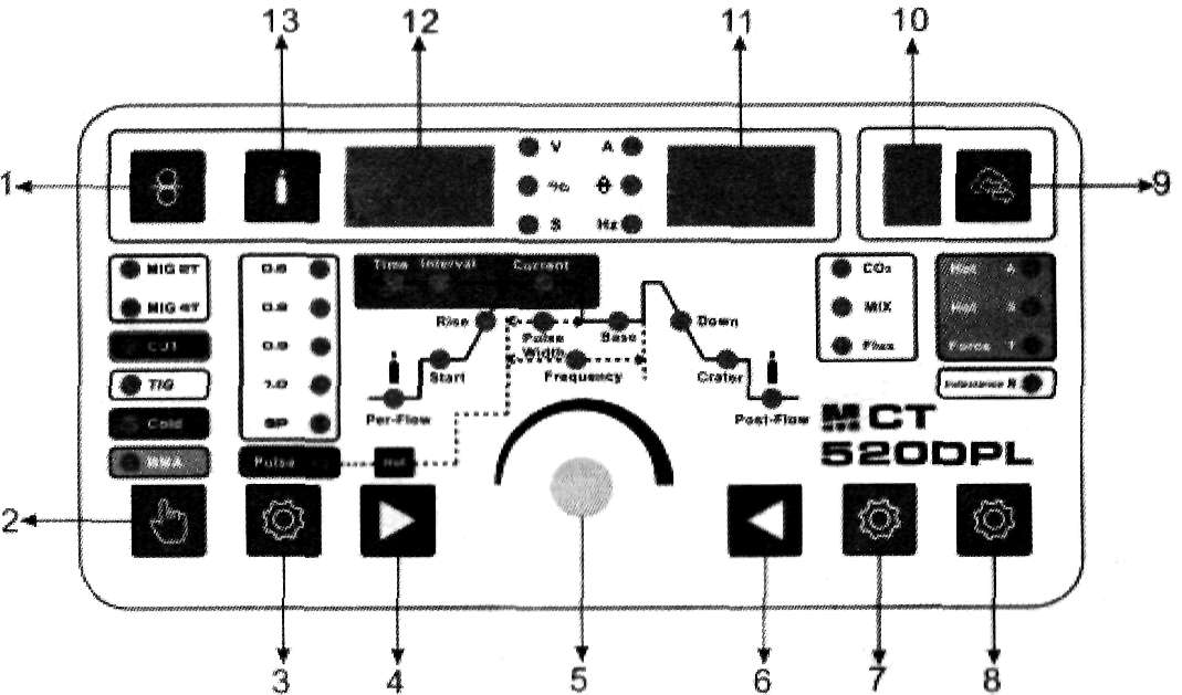
5.PANEL FUNCTION INSTRUCTION
5.1 Button function
Option function button: When the function button is selected as "CUT" mode or the indicator light is CUT, it can cut the iron plate for the cutting function; when the function button is set to "TIG" mode or the indicator light Is for TIG, it is DC argon arc welding. It can weld stainless steel, iron, copper and other metals.
When switching to MIG process, the welder can use 2T or 4T torch latch function for
Stainless Steel, Iron welding.
MMA/CUT/TIG function button: it is manual melt arc when the function button selected as "MMA".
5.2 Parameter adjustment (by the arrow button)
5.2.1 Pre-flow gas time parameter adjustment:^ order to ensure the welding effect, argon is required to arrive earlier than the current during welding. This parameter is to adjust the interval between the argon out and the arc.
5.2.2 Current adjustment: it is welding current
5.2.3 Attenuation parameter adjustment:When completing a section of welding and ending the arc, in order to ensure good forming, the current is required to gradually decrease to stop. This parameter is used to adjust the decay time of the current.
Note:When using the "foot pedal" control, this knob is turned counterclockwise to "0"
5.2.4 After flow gas time parameter adjustment:The workpiece after welding is oxidized by the heat, so after the welding is stopped, the argon gas blown by the welding torch is used for a certain period of time. This parameter is the time after the exhaust gas is adjusted, and the maximum time can be 10 seconds.
5.2.5 In "MMA" mode,only the welding current, the hot start, arc force, and other functions do not work.
5.3 Indicator light
Overheat protection indicator: When the welder is working continuously, for a long time or at a high current, the overheat protection function is set to prevent damage to the device due to internal heat. When the light is on, the digital display shows -E2, stop working, but not Shut down, after about 2-3 minutes the device can be automatically restored.
MIG Synergic/MIG Manual/TIG PULSE Selection: Press to select MIG Synergic mode (wire diameter) or MIG Manual mode or DC Pulse TIG
4
TIG Parameter Selection Button: Press to select different TIG parameters (move right)
5
Parameter Adjust Knob: Adjust to increase or decrease various parameters
6
TIG Parameter Selection Button: Press to select different TIG parameters (move left)
7
Function Selection Button: Press to select CO2 / mixed gas / gasless in MIG mode, or VRD in MMA mode, or 2T/4T trigger in TIG mode
8
Function Selection Button: Press to select Hot-start / Hot-start time / Arc-force in MMA mode, or Inductance in MIG mode, or 2T/4T trigger in CUT mode
9
Job Storage Button: Press to call the saved job (total 10 groups of jobs). Parameters of one job will be saved after 5 seconds without adjustment
10
Digital Display for Job Number
11
Digital Display for Current, Wire Feeding Speed, Hertz
12
Digital Display for Voltage, Pulse Width, Pulse Time
13
Gas Check Button
6.INSTALLATION INSTRUCTION
The machine is equipped with power voltage compensation device. When the power voltage fluctuates between±15% of rated voltage, it still can work normally.
When the machine is used with long cables, in order to prevent voltage form going down, bigger section cable Is suggested. If the cable is too long, it may have great affluence on the arc-striking or other performance of cutting system, e.g. the HF arc-striking performance get weak or the system work abnormally. So cables of configured length are suggested.
6.1 Make sure intake of the machine is not blocked or covered to avoid malfunction of cooling system.
6.2 Connect the protective gas source. The gas supply passage shall include a gas cylinder, an argon gas pressure reducing flowmeter and a gas pipe. The connecting portion of the gas pipe shall be fastened with a hose clamp or other articles to prevent argon gas leakage and air ingress.
6.3 Ground the cables with section area no less than 6mm2 to the housing, the way is connecting screw in the back of the power source to ground device, or make sure ground terminal of power socket is firmly connected. Both ways can be used for absolute safety.
6.4 Plug the quick plug of the loop cable into the quick socket of the welder panel with a polarity of "+" and follow The hour hand is tightened tightly, and the ground wire clamp at the other end clamps the workpiece
6.5 When using the foot switch control, connect the two-core aviation and three-core aviation plugs of the foot switch to the three-core air socket of the local panel.
6.6 According to the input voltage level of the welding machine, connect the power line to the distribution box of the corresponding voltage level. Do not connect the wrong voltage. Also ensure that the error of the power supply voltage is within the allowable range.
6.7 When using manual arc welding, install the electrode holder as shown. After the above work
is completed, the welder is finished. In the installation work, welding is available.
7.OPERATION INTRODUCTION
7.1 Use AC TIG welding function description:
7.1.1 Turn on the power switch and the fan inside the machine starts to rotate.
7.1.2 Press the function button and select the desired function to operate.
7.1.3 Turn on the argon switch and adjust the gas flow to the rated standard (see flow meter).
7.1.4 Adjust the ratio of positive and negative current time according to the degree of oxidation of the surface of the workpiece to be welded.
7.1.5 Press the switch on the torch and the solenoid valve starts. You will hear the high-frequency spark discharge in the welder. At the same time, there is argon gas flowing out of the torch nozzle. Note: When welding for the first time, you need to press and hold the switch for a few seconds before soldering until all the air in the air path is drained. After you stop welding, there will still be argon flow out in a few seconds. This is specially designed to ensure that the solder joints are protected before cooling. Therefore, after use, the welding position must be kept for a while after the arc is extinguished. Open the welding torch.
7.1.6 Adjust the "preflow", "postflow" and "down slop" times according to actual needs.
7.1.7 Keep the tungsten electrode and the welding workpiece at a distance of 2-4mm. Press the torch control switch to generate high-frequency discharge between the torch electrode and the workpiece. After the ignition starts, the high-frequency arc spark in the welder It disappears immediately and you can start working.
7.2 Use DC TIG welding function description:
7.2.1 Turn on the power switch and the fan inside the machine starts to rotate.
7.2.2 Press the function key to select the TIG function.
7.2.3 Turn on the argon switch and adjust the gas flow to the rated standard (see flow meter). 4. 5, 6, 7, and 8 in the same description.
7.3 Use DC MMA welding function description:
7.3.1 Turn on the power switch and the fan inside the machine starts to rotate.
7.3.2 Place the "TIG/MMA" switch in the "MMA" position. Determine the appropriate welding
current based on the thickness, station and process conditions of the welded workpiece. 7.3.3 The welding eledctrode clamped by electrode holder can be welded.
WARNING:
It is strictly forbidden to insert or remove any cable or connector in use during the welding process. This operation will endanger personal safety and cause serious damage to the equipment.
8.MAINTENANCE
WARNING:
Power must be turned off for all checking and maintenance, before opening the housing, make sure the power plug Is disconnected.
8.1 Remove dust by dry and clean compressed air regularly, if welding machine is operating in environment where is polluted with smokes and pollution air, the machine need removing dust everyday.
8.2 Pressure of compressed air must be inside the reasonable arrangement in order to prevent damaging to small components of inter-machine.
8.3 Check inter circuit of welding machine regularly and make sure the cable circuit is connected correctly and connectors are connected tightly (especially insert connector and components). If scale and loose are found, please give a good polish to them, then connect them again tightly.
8.4 Avoid water and steam enter into inter-machine, if they enter into machine, please dry inter-machine then check insulation of machine.
8.5 If welding machine will not be operated long time, it must be put into packing box and store in dry environment.
8.6 When wire machine operates for every 300 hours, the electric carbon brush and armature rectifier should be polished, the reducer should be cleaned, and lubricator should be added to the turbo and bearing.
9.NOTES BEFORE CHECKING
WARNING:
Blind experiment and careless repair may lead to more problems and make formal check and repair more difficult. When the machine is electrified, the bared parts contain life-threatening voltage. Any direct and indirect touch will cause electric shock, and severe electric shock will lead to death.
NOTICE:
In the period of guarantee maintenance, if user makes wrong check and repair for malfunction of welding/cutting machines without our permission, the free maintenance guarantee offered will be invalid
10. PRECAUTIONS
10.1 Surroundings
10.1.1 The welding operation should be carried out in a relatively dry environment, and the air humidity should generally not exceed 90%.
10.1.2 The ambient temperature should be between -10C and 40C.
10.1.3 Avoid welding in daylight or rain, and do not allow water or rain to seep into the welder.
10.1.4 Avoid welding work in dusty areas or in corrosive atmospheres. Avoid gas-shielded welding operations in environments with strong air flow.
10.2 Safety
10.2.1 Overvoltage, overcurrent and overheat protection circuits have been installed in our welding machine. When the grid voltage, output current and internal temperature exceed the set standard, the welder will automatically stop working; but excessive use (such as voltage over High) will still cause damage to the welder, so you still need to pay attention to the following matters
10.2.2 Ensure good ventilation
Our welding machine is a small welding machine. When operating, there is a large working current, and natural ventilation can not meet the cooling requirements of the welding machine. Therefore, a fan Is installed to effectively cool the welding machine to make it work smoothly. The user should confirm that the ventilation is not covered or blocked, and the distance between the welder and the surrounding objects should be no less than 0.3 meters. The user should always pay attention to maintain good ventilation, which is better for the welder and guarantees a longer service life, very important.
10.2.3 No current overload
The user should remember to observe the maximum allowable load current (relatively selectable
load continuation rate) and keep the welding current not exceeding the maximum allowable load
current.
Current overload will significantly shorten the life of the welder and may even burn the welder.
10.2.4 No too high voltage
The power supply voltage is listed in the "Main Performance Parameters" table. Under normal circumstances, the voltage automatic compensation circuit in the welder will ensure that the welding current is kept within the allowable range. If the power supply voltage exceeds the allowable value, the welder will be damaged and the user should fully understand the situation and take appropriate precautions.
10.2.5 A grounding screw is attached to the rear of each welder and marked with a grounding mark. Before use, use a cable with a section larger than 6mm2 to reliably ground the welder's casing to discharge static electricity or prevent accidents due to electric leakage.
10.2.6 If the welder exceeds the standard load continuation rate during operation, the welder may suddenly enter the protection state and stop working. This means that the welder exceeds the standard load continuation rate. Excessive heat energy triggers the temperature control switch, causing the welder to stop working while being in front. The red indicator light on the panel lights up. In this case, you do not have to unplug the power supply so that the cooling fan can continue to work to cool the welder. When the red indicator light goes out, the temperature drops to the standard range and the welding can be restarted.
ll.QUESTIONS TO BE RUN INTO DURING CUTTING
The phenomena listed here may be related to the accessories, gases, environmental factors, and power supply conditions you are using. Please try to improve the environment and avoid such situations.
11.1 the solder joint is black
In such cases, the solder joint is not protected well and is oxidized. You can check as follows:
11.1.1 Confirm that the valve of the argon cylinder is open and has sufficient pressure. If the pressure inside the bottle is less than 0.5MPa, it is necessary to refill the cylinder.
11.1.2 Check that the argon flow is on and has sufficient flow. To save gas, you can choose different flow rates depending on the welding current process, but too small a flow rate may result in insufficient shielding gas to cover the solder joints. We recommend that you do not let the argon flow rate be less than 31 / min, no matter how small the current is.
11.1.3 The easiest way to check if there is gas is to use the hand to feel the gas flow from the nozzle of the torch, check whether the gas path of the torch is blocked.
11.1.4 The gas path has a problem of poor sealing, or the purity of the gas is not high, which may cause welding quality problems.
11.1.5 If the environment has strong air flow, it may also cause the welding quality to drop.
11.2 Difficut to ignite arc, and easy to break the arc:
Confirm that the tungsten you are using is of good quality. The discharge capacity of a poor quality tungsten electrode may not meet the requirements.
A tungsten electrode that has not been sharpened is also less prone to arcing and causes arc instability.
11.3 the output current does not reach the rated value:
Deviation of the supply voltage from the rated value will cause the output current value to be inconsistent with the set value; when the supply voltage is lower than the rated value, the maximum output current of the welder may also be lower than the rated value.
11.4 The current cannot be kept stable during the use of the welder:
This situation may be related to the following factors:
11.4.1 The grid voltage changes.
11.4.2 Serious interference from the power grid or other electrical equipment.
11.5 cutting can not penetrate the steel plate:
11.5.1 Current regulation error.
11.5.2 The air pressure is insufficient.
12.TROUBLESHOOTING AND FAULT FINDING
MCT-520DPL
Fault symptom
Remedy
The power indicator does not light, the fan does not turn, no welding output
1. The power switch is broken.
2. Confirm that the power grid connected to the input cable has power.
3. Check if the input cable has a break.
The power switch indicator is on, the fan does not turn or rotates for a few times to stop, no welding output
1. It is possible to input the wrong connection on the 380V power supply, causing the overvoltage protection circuit to start, and then reconnect It to the 220V power supply and restart it.
2, 220V power is unstable (the input line is too long) or the input line is connected to the power grid, causing the overvoltage protection circuit to start, increasing the wire diameter of the grid input line or fastening the input line node. This phenomenon is in shutdown 2 - After 3 minutes, the new boot will return to normal.
3. Continuously open and close the power switch in a short time, causing the overvoltage protection circuit to start. Wait for 2-3 minutes and then restart it.
4. The wires between the switch and the power board are loose and retightened.
5. The main circuit 24V relay on the power supply board is not connected or damaged, check the 24V power supply and relay.
The fan turns, the abnormal indicator light is not bright, there is no high-frequency discharge "sa sa sa" sound, and the "arc welding" can not start the arc.
1. The voltage of the positive and negative poles of the VH-07 plug-in of the multimeter to the MOS board should be about DC308V.
2. The auxiliary power supply on the MOS board has a green indicator light. If the light is not on, the auxiliary power supply is not working. Look for the fault point or contact the dealer.
3. Check the poor connection of various patch cords in the machine.
4. Control circuit problems, find the cause or contact the dealer.
5. The control line on the welding torch is broken.
The abnormal indicator light is not lit, there is a high-frequency discharge "sa sa sa" sound, no welding output.
1. The welding gun cable is broken.
2. The ground wire is broken or not connected to the welded workpiece.
3. The positive output terminal or the welding torch gas output terminal is loose from the connection inside the machine.
Abnormal indicator light does not light, no high frequency discharge "sa sa sa" sound, "LIFT TIG welding" can start arc
1. The primary line of the arcing transformer has poor contact with the power board and is retightened.
2. The discharge nozzle is oxidized or the distance is remote. The surface oxide film of the discharge nozzle is treated or the distance of the discharge nozzle is adjusted to 1 mm.
3. The Individual components of the high-frequency arc-ignition circuit are damaged, and the replacement found.
Abnormal indicator light is on, no output
1. It may be overcurrent protection. Please turn off the machine. When the abnormal indicator light Is off and then restarted, it can be restored.
2, may be overheat protection, do not need to shut down for 2-3 minutes, the machine can naturally return to normal.
3. It may be that the inverter circuit is faulty. Please unplug the power supply plug of the main transformer on the MOS board (near the fan VH-07 plug-in) and restart it:
(1) If the abnormality indicator is still on, turn off the power plug of the high-frequency pilot arc power supply (near the fan VH-03 plug-in) and turn it back on:
a. If the abnormal indicator is still on, the individual FETs on the MOS board are damaged.
b. If the abnormal indicator is not lit, the step-up transformer in the high-frequency arc-rising circuit on the power supply board is broken and replaced. (2) If the abnormal indicator does not light:
a. It may be damaged in the middle plate transformer. The primary inductance and Q value of the main transformer can be measured by the bridge,
b. It may be that the transformer secondary rectifier is individually broken down, and the same type of rectifier is found and replaced.
4. It may be that the feedback circuit is open.
Can not break the oxide film when welding aluminum
1. The welding gear selection is incorrect;
2. The duty cycle adjustment is too small;
3. The secondary inverter has field tube damage.
Tungsten needle burnt seriously
The duty cycle is adjusted too much to reduce the duty cycle.
Fault symptom
Exclude
The fan does not rotate, the digital meter has no display, and there is no welding output.
1. Confirm that the air switch is Intact or closed.
2. Confirm that the power grid connected to the output cable has power.
3. The thermistor (four) on the power supply board is damaged (this is usually caused by DC24V relay failure or poor contact contact).
4. The power board (base board) is faulty and there is no DC537V voltage output.
5. The auxiliary power supply on the control panel has failed.
The fan turns, the abnormal indicator light is not bright, there is no high-frequency discharge "sa sa sa" sound,
and the "LIFT TIG welding" can not start the arc.
1. Check all kinds of patch cords in the machine for poor contact.
2. Control circuit problems, find the cause or contact the dealer.
3. The control line on the welding torch is broken.
Abnormal indicator light is off, there is high frequency discharge "sa sa sa" sound, no welding output
1. The welding gun cable is broken.
2. The ground wire is broken or not connected to the welded workpiece.
3. The positive output terminal or the torch gas output terminal is loose from the connection inside the machine.
Abnormal indicator light is not lit, no high-frequency discharge "sa sa sa" sound, arc welding can start arc
1, The primary line of the arcing transformer is in poor contact with the arcing plate and is retightened.
2. The discharge nozzle is oxidized or the distance is remote. The surface of the discharge nozzle is treated with an oxide film or the distance of the discharge nozzle is about 1 mm.
3. Hand soldering argon welding conversion switch is damaged and replaced.
4. The individual components of the high-frequency arc-trigger circuit are damaged, and the replacement is found.
Abnormal indicator light is on, no output
1. It may be overcurrent protection. Please turn off the machine. When the abnormal indicator light is off and then restarted, it can be restored.
2, may be overheat protection, do not need to shut down for 2-3 minutes, the machine can naturally return to normal.
3. It may be that the inverter circuit is faulty. Please unplug the power supply plug of the main transformer on the MOS board (near the fan VH-07 plug-in) and
restart it:
(1) If the abnormality indicator is still on, turn off the power plug of the high-frequency pilot arc power supply (near the fan VH-03 plug-In) and turn it back on:
a. If the abnormal indicator is still on, the individual FETs on the MOS board are damaged.
b. If the abnormal indicator is not lit, the step-up transformer in the high-frequency arc-rising circuit on the power supply board is broken and replaced.
(2) If the abnormal indicator does not light:
a. It may be damaged in the middle plate transformer. The primary inductance and Q value of the main transformer can be measured by the bridge.
b. It may be that the transformer secondary rectifier is individually broken down, and the same type of rectifier Is found and replaced.
4. It may be that the feedback circuit is open.
Tungsten needle burnt seriously
The duty cycle is adjusted too much to reduce the duty cycle.
Can not break the oxide film when welding aluminum
 On the process of welding or cutting, there will be possibility of injury, so please take protection into consideration during operation. For more details please review the Operator Safety Guide, which complies with the preventive requirements of the manufacturer.